Introduction
Welding symbols are essential in the construction and manufacturing industries, serving as a universal language for welders, engineers, and inspectors. These symbols provide critical information about the type, size, and other specifications of welds required for a project, ensuring that all involved parties can execute and verify welds accurately and efficiently. This guide aims to help readers understand and accurately interpret basic welding symbols, enhancing their ability to work with technical drawings and maintain high standards of quality and safety in their projects.
What Are Welding Symbols?

Welding symbols are a standardized method of representing welding requirements on technical drawings. They convey detailed instructions about the type of weld, its size, and other specifications without the need for extensive written descriptions. This standardization allows for clear communication across different languages and technical disciplines, ensuring that welders, engineers, and inspectors can easily understand the requirements.
Welding symbols are crucial because they:
- Ensure Consistency: By using standardized symbols, everyone involved in the welding process can understand the requirements without ambiguity.
- Save Time: Clear and concise symbols reduce the time needed to interpret welding instructions, speeding up the production process.
- Improve Quality Control: Accurate interpretation of welding symbols helps prevent errors and defects, leading to higher-quality welds and safer structures.
Understanding the basic components and common types of welding symbols is the first step in mastering their use.
Components of a Welding Symbol
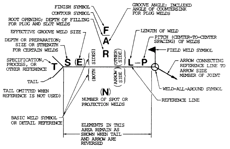
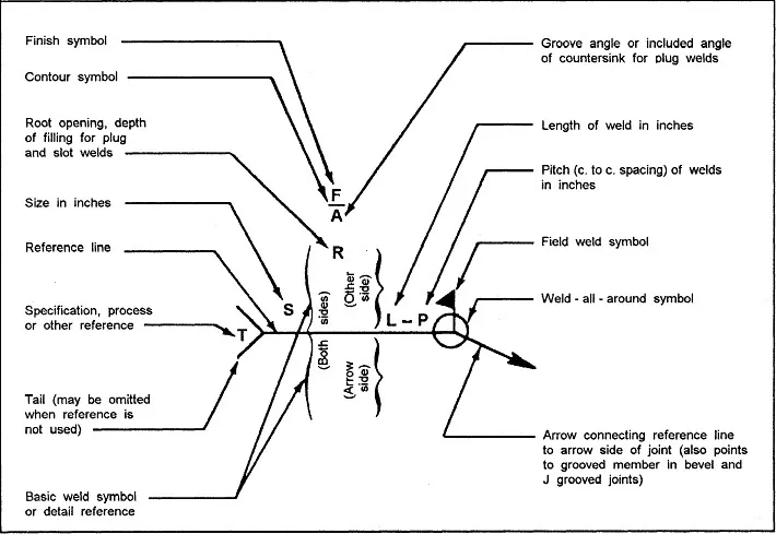
A welding symbol is composed of several key elements, each providing specific information about the weld. The main components include:
- Reference Line: The horizontal line that serves as the foundation of the welding symbol. All other elements of the symbol are connected to this line.
- Arrow: Points to the location on the drawing where the weld is to be made. The direction of the arrow indicates whether the weld is on the near side or the far side of the joint.
- Tail: An optional part of the symbol used to provide additional information or specify a welding process.
- Weld Size, Length, and Spacing: These elements are often included to give precise dimensions and intervals for the welds.
Common Welding Symbols
Understanding common welding symbols is crucial for anyone involved in welding projects. Here are some of the most frequently encountered symbols:
- Fillet Weld: Represented by a triangular symbol, fillet welds are used to join two surfaces at a right angle to each other. These are common in T-joints, lap joints, and corner joints. The symbol indicates the size of the weld leg and the length of the weld.
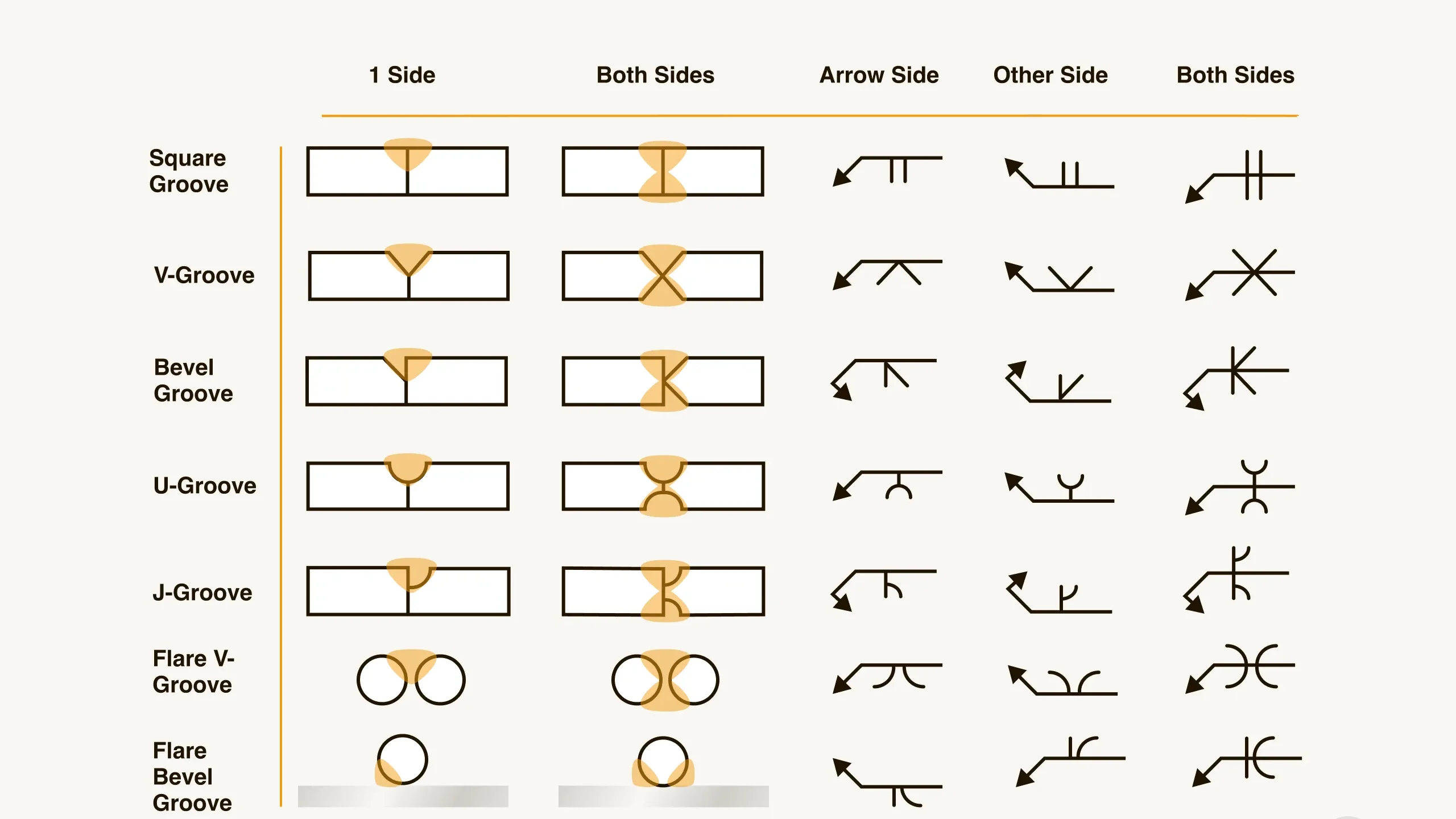
- Groove Weld: Groove welds are used to join two pieces of metal edge-to-edge. There are several types of groove welds, including V-groove, U-groove, J-groove, and bevel groove. Each type is represented by a specific symbol that indicates the shape of the groove and its dimensions.
- Butt Weld: This is a simple weld where two pieces of metal are joined in a straight line. The symbol for a butt weld can vary depending on the specific type of groove used (e.g., V-groove, square groove).
- Plug and Slot Welds: These welds are used to join two overlapping pieces of metal by welding through holes (plug) or slots in one piece into the other. The symbols for plug and slot welds include details about the size and spacing of the holes or slots.
- Spot and Seam Welds: These welds are used for joining thin materials by creating small weld points (spot) or continuous welds (seam) along a joint. The symbols indicate the size and spacing of the spots or seams.
How to Read Welding Symbols

Interpreting welding symbols correctly is vital for ensuring that welds are made to the specified requirements. Here is a step-by-step guide to reading welding symbols:
- Identify the Reference Line: The reference line is the starting point for interpreting the symbol. It provides the baseline from which all other elements are positioned.
- Follow the Arrow: The arrow points to the location of the weld on the drawing. The side of the reference line that the arrow points to indicates where the weld should be made (near side or far side).
- Read the Weld Symbol: The weld symbol itself will indicate the type of weld (e.g., fillet, groove). Pay attention to the shape and any additional lines or symbols attached to the main weld symbol.
- Check for Additional Information: Look at the tail for any supplementary information, such as the welding process to be used or any special instructions.
- Note the Dimensions: Ensure you understand the size, length, and spacing details provided with the weld symbol. These dimensions are critical for creating the correct weld.
- Interpret Any Supplementary Symbols: Additional symbols may indicate requirements like weld finish, contour, or backing.
Example
Consider a simple example with a fillet weld symbol:
- The reference line runs horizontally across the drawing.
- An arrow points to the location of the weld.
- A triangular symbol on the reference line indicates a fillet weld.
- The size of the fillet weld is specified on the left side of the symbol, and the length is specified on the right.
Practical Applications
Understanding welding symbols is not just about recognizing them on paper; it’s also about knowing how to apply this knowledge in real-world scenarios. Here are some practical applications of welding symbols:
- Engineering Drawings: In engineering drawings, welding symbols are used to communicate detailed instructions for welders. These symbols ensure that all welds meet the design specifications and quality standards.
- Construction Projects: In construction, welding symbols are critical for building structures that are safe and reliable. For example, in the construction of bridges, buildings, and pipelines, precise welds are necessary to ensure structural integrity.
- Manufacturing: In manufacturing, welding symbols guide the assembly of metal parts. Whether it’s in the automotive industry, shipbuilding, or aerospace, welding symbols help maintain consistency and quality across production lines.
Example: Reading a Welding Symbol in an Engineering Drawing
Imagine an engineering drawing for a metal frame. The drawing includes several welding symbols that indicate where and how welds should be made.
- Fillet Weld Symbol: Located at the corner of two metal plates, the symbol includes a triangle indicating a fillet weld. The size of the fillet weld (e.g., 1/4 inch) is noted on the left side of the triangle, and the length of the weld (e.g., 3 inches) is on the right.
- Groove Weld Symbol: Along the edge of two metal plates that need to be joined end-to-end, the symbol includes a V shape indicating a V-groove weld. The depth of the groove and the included angle are specified.
- Spot Weld Symbol: On a section where thin sheets are overlapped, the symbol includes a circle indicating a spot weld. The diameter of the spot weld and the spacing between spots are detailed.
Common Mistakes and How to Avoid Them
Despite the clarity that welding symbols provide, mistakes can still occur. Here are some common errors and tips on how to avoid them:
- Misinterpreting the Arrow: One common mistake is not correctly identifying which side of the joint the weld should be applied to. Always follow the direction of the arrow carefully.
- Ignoring Dimensions: Failing to note the specific dimensions (size, length, spacing) can lead to incorrect welds. Pay close attention to all the numerical details provided with the symbols.
- Overlooking Supplementary Symbols: Additional symbols that indicate weld finish, contour, or backing are often missed. Ensure you review the entire welding symbol, including any supplementary information in the tail.
- Assuming Standard Procedures: Sometimes, welders assume standard procedures without checking for specific instructions. Always verify if there are any special requirements or processes indicated in the tail of the symbol.
- Inadequate Training: Lack of proper training in reading and interpreting welding symbols can lead to mistakes. Regular training and practice are essential for maintaining accuracy.
Standardization and Variations

Welding symbols are standardized by various codes and standards to ensure uniformity and clarity across different regions and industries. Some of the primary standards include:
- American Welding Society (AWS): AWS provides a comprehensive set of standards for welding symbols used primarily in the United States.
- International Organization for Standardization (ISO): ISO standards are used internationally, providing guidelines for welding symbols that may differ slightly from AWS standards.
International Differences
While the basic principles of welding symbols are similar worldwide, there can be notable differences in how they are represented and interpreted in different countries. It’s essential to be aware of these variations if you’re working on international projects.
How to Read Welding Symbols
Interpreting welding symbols accurately is essential for ensuring that the welds meet the specified requirements. Here’s a step-by-step guide on how to read welding symbols:
- Identify the Reference Line: Start by locating the reference line, which serves as the baseline for the welding symbol. All other elements will be connected to or placed above and below this line.
- Follow the Arrow: The arrow points to the specific location on the drawing where the weld is to be made. It indicates whether the weld is to be applied to the near side (arrow side) or the far side (opposite the arrow).
- Read the Weld Symbol: Look at the symbol attached to the reference line. The shape and orientation of this symbol will tell you the type of weld required. For example, a triangular symbol represents a fillet weld, while a V shape indicates a V-groove weld.
- Check for Dimensions: Examine any numbers associated with the weld symbol. These numbers provide crucial information about the size, length, and spacing of the weld. For instance, a number to the left of the symbol typically indicates the weld size, while a number to the right indicates the weld length.
- Interpret Supplementary Symbols: Additional symbols or notations might be present to convey further details. These can include:
- Finish Symbols: Indicating the desired finish for the weld (e.g., grinding, machining).
- Contour Symbols: Specifying the shape of the finished weld (e.g., convex, concave).
- Backing or Root Symbols: Providing information on backing materials or root conditions.
- Review the Tail: If present, the tail of the welding symbol can contain additional information such as welding process (e.g., SMAW, MIG), specifications, or any other special instructions. If there is no additional information, the tail may be omitted.
Example: Reading a Complete Welding Symbol
Consider a complete welding symbol for a fillet weld on an engineering drawing:
- Reference Line: A horizontal line running across the drawing.
- Arrow: Points to the location of the weld, indicating it should be made on the arrow side.
- Weld Symbol: A triangular shape on the reference line, indicating a fillet weld.
- Dimensions:
- The number “1/4” on the left side of the triangle, indicating a 1/4 inch fillet weld.
- The number “3” on the right side of the triangle, indicating the weld should be 3 inches long.
- Supplementary Symbols:
- A grind finish symbol (indicated by a horizontal line with a tail) showing that the weld needs to be ground flush.
- Tail: Contains the notation “SMAW” indicating that Shielded Metal Arc Welding is to be used.
Conclusion
In this article, we’ve covered the fundamentals of understanding and interpreting basic welding symbols. These symbols are a vital part of ensuring that welding tasks are performed correctly and to the necessary specifications. By learning how to read and apply these symbols accurately, welders, engineers, and inspectors can improve the quality and safety of their projects.
- Summary: Welding symbols provide a universal language for conveying detailed welding instructions, ensuring consistency, efficiency, and quality control.
- Final Thoughts: Mastering welding symbols is essential for anyone involved in welding-related projects. Accurate interpretation and application of these symbols can prevent errors and defects, leading to better, safer welds.
- Call to Action: Encourage readers to practice interpreting welding symbols and consider further education or certification in welding for advanced knowledge and skills.
Additional Resources
- Books and Guides: Recommend further reading materials like “The Welding Handbook” by the American Welding Society or “Welding Symbols Quick Card” by Builder’s Book Inc.
- Online Courses: Suggest online courses or tutorials on platforms like Coursera, Udemy, or Khan Academy.
- Professional Organizations: Provide information about relevant professional organizations like the American Welding Society (AWS) and the International Institute of Welding (IIW) for certifications and further learning opportunities.
Leave a Reply